LogicCircuit - X 64-bit Download
Popular x64 Tags
- calculator x64 download
- tool x64 download
- freeware x64 download
- free x64 download
- software x64 download
- download x64 download
- radio x64 download
- data x64 download
- ebook x64 download
- home inventory x64 download
- planner x64 download
- windows x64 download
- free numerology software x64 download
- free numerology x64 download
- reg software x64 download
- numerology software x64 download
- numerology x64 download
- auto repair help x64 download
- passwords x64 download
- chicken coop plans x64 download
- numerology reading x64 download
- blood pressure x64 download
- automobile x64 download
- github x64 download
- 3d modeling x64 download
- viewer x64 download
- automation x64 download
- open source x64 download
- auto x64 download
- open-source x64 download
LogicCircuit 2.25.06.10
Sponsored links:
license: Open Source
downloads: 377
size: 57.60 MB
updated: 2025-06-13
tags: Logical Circuit, download Logical Circuit, Logical Circuit free download, Design Logical Circuit, Simulate Logical Circuit, Logical Circuit Designer, Circuit, Designer, Design, Simulate
Add to Basket
Eugene Lepekhin

Logical Circuit, developed by Eugene Lepekhin, is a sophisticated yet user-friendly software tool designed for those interested in digital logic design and simulation. This application serves as an invaluable resource for students, educators, and hobbyists who are keen on exploring the intricacies of digital circuits without the need for physical components.
At its core, Logical Circuit offers a robust platform for designing and simulating digital circuits. The software provides a comprehensive suite of tools that allow users to create complex logic gates, flip-flops, multiplexers, and other essential components of digital electronics. Its intuitive drag-and-drop interface simplifies the process of circuit design, making it accessible even to beginners who may not have extensive experience in electronics.
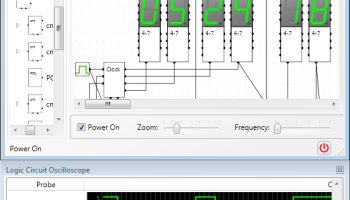
One of the standout features of Logical Circuit is its real-time simulation capability. Users can test their circuits and observe the behavior of signals as they propagate through the system. This dynamic simulation environment is instrumental in helping users understand how changes in the circuit design affect overall performance, providing immediate feedback that is crucial for learning and experimentation.
Logical Circuit also supports hierarchical design, allowing users to create modular circuits that can be reused and integrated into larger systems. This feature is particularly beneficial for more advanced users who are working on complex projects and need to manage multiple layers of circuit design efficiently.
The software is equipped with a variety of educational tools, including a built-in oscilloscope and logic analyzer, which aid in the visualization and analysis of circuit behavior. These tools are essential for diagnosing issues and refining circuit designs, offering users a deeper insight into the functioning of their digital creations.
Moreover, Logical Circuit is highly customizable, with options to tailor the interface and functionality to suit individual preferences and project requirements. This flexibility ensures that users can optimize their workflow and focus on the creative aspects of circuit design.
While Logical Circuit is a powerful tool, it maintains a lightweight footprint, ensuring that it runs smoothly on a wide range of computer systems without demanding excessive resources. This makes it an ideal choice for users who need a reliable and efficient digital circuit design tool that doesn't compromise on performance.
In summary, Logical Circuit by Eugene Lepekhin is a versatile and comprehensive software solution for anyone interested in digital logic design. Its combination of ease-of-use, powerful simulation capabilities, and educational tools make it an excellent choice for both beginners and experienced users. Whether you're a student learning the basics of digital electronics or a seasoned professional looking to prototype complex circuits, Logical Circuit provides the tools and flexibility needed to bring your digital designs to life.
At its core, Logical Circuit offers a robust platform for designing and simulating digital circuits. The software provides a comprehensive suite of tools that allow users to create complex logic gates, flip-flops, multiplexers, and other essential components of digital electronics. Its intuitive drag-and-drop interface simplifies the process of circuit design, making it accessible even to beginners who may not have extensive experience in electronics.
One of the standout features of Logical Circuit is its real-time simulation capability. Users can test their circuits and observe the behavior of signals as they propagate through the system. This dynamic simulation environment is instrumental in helping users understand how changes in the circuit design affect overall performance, providing immediate feedback that is crucial for learning and experimentation.
Logical Circuit also supports hierarchical design, allowing users to create modular circuits that can be reused and integrated into larger systems. This feature is particularly beneficial for more advanced users who are working on complex projects and need to manage multiple layers of circuit design efficiently.
The software is equipped with a variety of educational tools, including a built-in oscilloscope and logic analyzer, which aid in the visualization and analysis of circuit behavior. These tools are essential for diagnosing issues and refining circuit designs, offering users a deeper insight into the functioning of their digital creations.
Moreover, Logical Circuit is highly customizable, with options to tailor the interface and functionality to suit individual preferences and project requirements. This flexibility ensures that users can optimize their workflow and focus on the creative aspects of circuit design.
While Logical Circuit is a powerful tool, it maintains a lightweight footprint, ensuring that it runs smoothly on a wide range of computer systems without demanding excessive resources. This makes it an ideal choice for users who need a reliable and efficient digital circuit design tool that doesn't compromise on performance.
In summary, Logical Circuit by Eugene Lepekhin is a versatile and comprehensive software solution for anyone interested in digital logic design. Its combination of ease-of-use, powerful simulation capabilities, and educational tools make it an excellent choice for both beginners and experienced users. Whether you're a student learning the basics of digital electronics or a seasoned professional looking to prototype complex circuits, Logical Circuit provides the tools and flexibility needed to bring your digital designs to life.
OS: Windows 11, Windows 10 32/64 bit, Windows 8 32/64 bit, Windows 7 32/64 bit
Add Your Review or 64-bit Compatibility Report
Top Other 64-bit downloads


Flexify 2.1.64

Flexify: A versatile tool for seamless data manipulation and integration.
Open Source


Rocrail 2026-03-15 Revision
Rocrail: Open-source model railroad control software for automation and control.
Open Source

stretchly 1.20.0
Boost productivity with Stretchly, a break reminder app for healthier work.
Open Source


WinStars 3.0.304 (2025
Explore the cosmos with WinStars, your interactive astronomy software.
Freeware

Offline Map Maker 8.381
Create detailed offline maps from online sources with ease and precision.
Demo | $79.00

Members area
Top 64-bit Downloads
-
Fitbit Connect 2.0.2.7066
x64 freeware download -
MyTourbook 64-bit 19.6.1
x64 open source download -
JAWS 64-bit 14.0.5005
x64 trialware download -
Money Manager Ex
Portable x64 1.8.0
x64 freeware download -
Moneydance x64 2017.8 (1691)
x64 trialware download -
Deeproot Plant Base X64 2.2.0
x64 shareware download -
Money Manager Ex x64 1.8.0
x64 freeware download -
Parabator 2 1.0
x64 freeware download -
Parabator 2 -
"perk" booster
mod 1.0
x64 freeware download -
Parabator 2
"perkk"
booster mod 1.0
x64 freeware download
Top Downloads
-
Netron 8.9.6
open source download -
Flexify 2.1.64
open source download -
Easy-PC 25.0.3.85
demo download -
Rocrail 2026-03-15 Revision
open source download -
stretchly 1.20.0
open source download -
fsmapper 1.6.5
open source download -
dwgConvert 2024 A.11
demo download -
Anki 25.07.2
open source download -
WinStars 3.0.304 (2025
freeware download -
Offline Map Maker 8.381
demo download -
IRIS 5.59
freeware download -
WriteMapper 4.5.0
demo download -
OpenComic 1.6.5
open source download -
CyberSky 5.1.1
shareware download -
Desktop Projector 3.4.7
freeware download